We appreciate your time on our website. Please help us grow by sharing our site with your friends and colleagues. Thank you for helping us build a stronger community!
Exhaust Gas Recirculation (EGR) System
Exhaust Gas Recirculation (EGR) is a way of drastically lowering NOx emissions. Tier III EGR has been proven to satisfy Tier III NOx criteria. Eco EGR is an engine mode that optimizes the SFOC in locations where the IMO Tier II NOx restrictions apply. Eco EGR is functionally comparable to Tier III EGR but has a lower EGR rate.
MAIN ENGINE
MARINE GEEK
6/20/20246 min read

The EGR system must be built to meet the IMO Tier III NOx regulations outlined in Revised MARPOL Annex VI and the NOx Technical Code 2008. The engine must meet an IMO NOx cycle value of 3.4 g/kWh for engines rated below 130 RPM (n) and 9 n-0.2 g/kWh for engines rated with n≥≥[130;1999] for the applicable load cycle. Furthermore, the not-to-exceed NOx limit (NTE) applies, implying that the particular NOx emission must not exceed 1.5 times the relevant cycle limit at any load point during the load cycle.
Working Principles
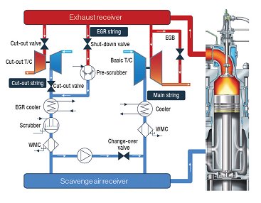
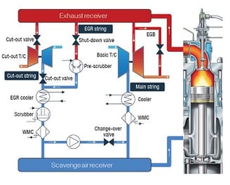
In the EGR system, after cooling and cleaning, a portion of the exhaust gas is routed to the scavenge air receiver. The result of this process is that some of the oxygen in the scavenge air is replaced by CO2 from burning. Therefore, the scavenge air's heat capacity is somewhat enhanced, resulting in a lower temperature peak during combustion. As a result, the amount of NOx generated in the combustion chamber is lowered.
When no EGR is present, the cooler and WMC are employed for the EGRTC portion of the EGR string. The most crucial thing to notice while understanding the EGRTC system type is that the TC must be cut-out before EGR starts, hence the TCV, CCV and BBV must be closed.
The EGR is activated by first starting the EGR blowers, then opening the EGR Shut Off Valve, and lastly the EGR Blower Throttle valve. Some exhaust gas is then sent back to the scavenge air receiver via the pre-spray and EGR unit, where it is cooled and cleaned. The EGR blower and BTV govern the quantity of gas recirculated, ensuring that the recorded oxygen levels in the scavenging air receiver match the levels of Tier III NOx emissions. If the auxiliary blowers are turned off, the cylinder bypass opens while the BTV is open. The recirculated exhaust gas is known as EGR Gas'.
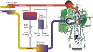
The mechanism for water cooling and cleaning the EGR gas may be observed. Three WHS layouts are illustrated.
WHS1: The WTS is responsible for supplying water of a specific quality to the recirculation loop. The recirculation loop is made up of the EGR unit, the Receiving Tank, and the Process Water Circulation Pump, as well as the SWSV and PWSV sealing valves. In WHS1, there is no EGR drain tank.
If you have an EGR HS-HFO system, the buffer tank in WHS2 is directly linked to the WTS.
In an EGR LS system, the WTS is not required to clean the water in the recirculation loop, hence the WTS is not linked to the buffer tank.
The WTS is not provided by MAN ES in all configurations, and the water is sent into the EGR Gas system via the water sprays before returning to the receiving tank via the EGR unit's drainage. WHS is almost same for the two EGR system types, EGR-BP and EGR-TC.
The EGR Water is initiated before the EGR Gas, ensuring that the EGR Gas is cooled and cleansed from the start. First, the WTS is activated (applicable to WHS1 and WHS2 LS), the buffer tank is filled (applicable to WHS2), and the input of treated water begins before the circulation of process water begins. Finally, the process water receiving tank level is controlled by the Receiving Tank Level Valve, while the pH is controlled by the NaOH dosing pump. In the case of WHS2 HS-HFO, the WTS is activated while EGR Water is flowing. MCDV and EUDV direct process water to the PWRT during EGR operation and to the bilge tank and air cooler drain tank, respectively, when EGR is not operating. When the EGR unit is turned off, the EUWV empties the water trap beneath it. EUDV and EUWV are only available on EGRTC systems.
EGR System Individual components
EGR with TC cut-out matching, equipped with two or more turbochargers and utilized on engines with a bore of 80 or more.
The engine-integrated EGR unit houses both the EGR cooler and the water mist catcher. The EGR water treatment system is not an integral component of the engine. In an EGR system with bypass matching, the turbocharger might be positioned on the exhaust side or aft. There are one or more EGR units, which include cut-out turbochargers and one or more basic turbochargers.
EGR Blower
The EGR blower transfers up to 40% of exhaust gas to the scavenging air receiver. At 100% engine load, the pressure differential between the receivers can reach 0.3 bar, and the EGR blower must overcome this pressure difference as well as pressure loss through the pre-spray, cooler, pipes, and other components, which ranges from 0.2 to 0.3 bar depending on engine load. The EGR blower speed is regulated by a frequency converter that operates on the blower motor.
EGR Blower Throttle Valve(s)
The cut-out valve(s) regulate the EGR flow in conjunction with the blowers. The failsafe position is closed and will be activated in the event of a power outage or a wire breakage.
EGR Blower system Bypass Valve
This may be thought of as a valve for regulating EGR gas while the system is in Tier lll mode. The valve stops the process gas from flowing back. If there is leakage (when shut), the EGR blower will not be able to provide an adequate flow. Only for EGRTC engines.
EGR Shut Off Valve
For turning on and off the flow of the EGR system, and therefore shutting down EGR operation. The valve is gas tight, preventing scavenge air from backflowing into the exhaust system when the EGR system is turned off. The valve is "on/off"-controlled. The safe position is closed in the event of a power outage or a wire breakage. During the EGR start process, the valve will transition from the fail safe position to open, and it will remain open throughout the EGR operation.
EGR Cylinder Bypass Valve
The cylinder bypass valve bypasses gas from the compressor exit to the turbine intake. The cylinder bypass valve may be seen of as a TC matching "tool". Its goal is to maintain a consistent scavenging air pressure. This is valid and desirable for both Tier ll and Tier lll operations. The valve position is changeable, allowing almost any gas flow volume to be properly used. The failsafe setting of the EGR Cylinder Bypass Valve is closed. In other words, if the power (air supply/current) fails or the wire breaks, the EGR Cylinder Bypass Valve will close.
Pre-spray
The exhaust gas is cleaned with recirculated fresh water containing sodium hydroxide (NaOH). NaOH neutralizes the sulphuric acid produced in the scrubber water by the SOx in the exhaust gas. Approximately 65% of the scrubber water is continually recirculated. Water evaporation cools the exhaust stream, and scrubber water is injected into the hot exhaust gas through injection nozzles to remove SOx and particulate particles. Parts of the water are evaporated, and the temperature is decreased from exhaust to around 80-100°C. After passing through the pre-spray, the mixture of cooled exhaust gas, steam, and scrubber water is sent to the EGR cooler.
EGR cooler
For cooling the EGR gas. The water evaporated in the pre-scrubber condenses in the EGR cooler. The EGR cooler cools the gas to about the scavenging air temperature.
EGR WMC
To separate the scrubber water from the EGR gas before it is blended with the standard air cooler air flow.
Sensor Unit (SU)
The Exhaust Gas Recirculation is equipped with Sensor Unit for measuring O2 content in the system.
Oxygen sensors 1-3
For measuring the oxygen concentration of the scavenge air receiver. The oxygen concentration in the scavenge air receiver controls the quantity of EGR gas produced, which ranges between 16 and 21% depending on engine mode and load.
Operation
The ME MOP, or alternatively the bridge, handles the EGR System's overall operation (start/stop), whilst the ERCS MOP handles the detailed operation and information. The Engine Mode is simply selected at the ME MOP or bridge, and the EGR Control System (EGR-CS) will start or stop the EGR system while the ME-ECS selects the corresponding Engine Running Mode (the Engine Running Mode is related to the timing of the fuel injection and should not be confused with the Engine Mode, which is a Tier II or Tier III selection). One Engine Mode can have many Engine Running Modes.
To do the aforesaid action from the ME MOP or the bridge, the EGR System must be in EGR Mode Auto. If a mistake occurs in the EGR System, the EGR Control System will shift the EGR Mode to Failure, which will be reset to Stop. Once the cause of the problem has been identified, the operator must manually reset the EGR Mode on the ERCS MOP to Auto. If the operator fails to do so, the EGR System will not operate, even if the Engine Mode is Tier III. The current condition of the EGR System is shown on the ERCS MOP, the ME MOP, and, optionally, the bridge. The operator can choose to switch the EGR Mode to Stop if it for some reason is desired to ensure that the EGR System doesn't start, regardless of the choices on the ME MOP or the bridge.
The operator must constantly maintain the sulfur equivalent of the fuel updated on the ME MOP, as this has an impact on the NaOH dosage in the EGR water. The real fuel sulfur equivalent is displayed on both the EGR Main Screen and the Water Auxiliary Screen. Furthermore, the NaOH concentration on the ERCS MOP must be updated at all times, since it has a significant influence on NaOH dosing requirement. It is located on the EGR Main Screen and the Water Auxiliaries screen, and the operator must be at the Chief level to change its value.